


1 Introduction
Several companies in the Pulp and Paper sector have started using RFID tags for identification of pulp products. RFID enables reliable and accurate identification of pulp products in modern logistics operations. RFID can be used to improve processes by automating unique identification of pulp units and enable full visibility of the movements of products in the supply chain. Many of the benefits from RFID identification of pulp products requires cooperation between different actors in the industry to fully benefit from the technology. Thus, a guideline for RFID implementation is needed in the industry.
This Guideline focuses on the main requirements regarding implementation to enable cooperation and usage of RFID identification between parties in Pulp and Paper Industry: Performance and readability requirements and the tag data encoding. Guideline for tag encoding is based on the GS1 SGTIN-96 format (Serialised GTIN).
Companies working in the Pulp and Paper sector should also consider implementing appropriate backup solutions in case the UHF RFID data carrier cannot be read or scanned. This can be done by using a GS1 linear or 2D data carrier with HRI. The way to implement such backup system is out of scope of this document.
2 Usage of UHF passive RFID
For identification of pulp products, this document requires usage of UHF passive RFID tags compliant with GS1 air interface protocol EPC™ Radio-Frequency Identity Protocols Generation-2 UHF RFID Standard, Specification for RFID Air Interface Protocol for Communications at 860 MHz – 960 MHz, Release 2.1, Ratified, Jul 2018
■ RFID tags applied to pulp products must conform to EPC Gen2 V2.1 requirements [3]
3 Functional Requirements
This guideline defines two possible ways of implementing RFID identification of pulp units: 1) Identifying bundled pulp units (typically 2tn units comprising of 8pcs of individual pulp bales) and 2) identifying the individual pulp bales (typically weighing approximately 250kg/bale).
This guideline specifies how the tag data should be encoded and what are the performance requirement for reading of the RFID tags in both cases. This guideline does not specify which methods of identification the parties implementing a system should use. Both methods of identification defined in this document have a separate requirement specification in this document. Those parties that decide to follow this guideline are free to choose which method of identification is suitable to their needs.
3.1 Functional requirements of the guideline for the tag solution:
■ Tag must withstand normal environmental conditions experienced in supply chain of the products (depending on the product specification)
■ Tag must withstand normal wear and tear, exposure to rain, during logistics operations (warehousing, loading/unloading, shipping)
■ Identification of bundled pulp units must be possible from at least 2 opposite sides of the unit to enable efficient logistics operations
■ Identification of individual pulp bales must be possible from at least 1 side (see Figure 4‑3 Reading from side (individual bale))
■ Metal wires used to bind pulp units together should not obstruct reading or limit reading range below required limits
4 Performance Requirements
4.1 Performance requirements for bundled pulp units (bundled bales)
4.2 Performance requirements for individual pulp bales
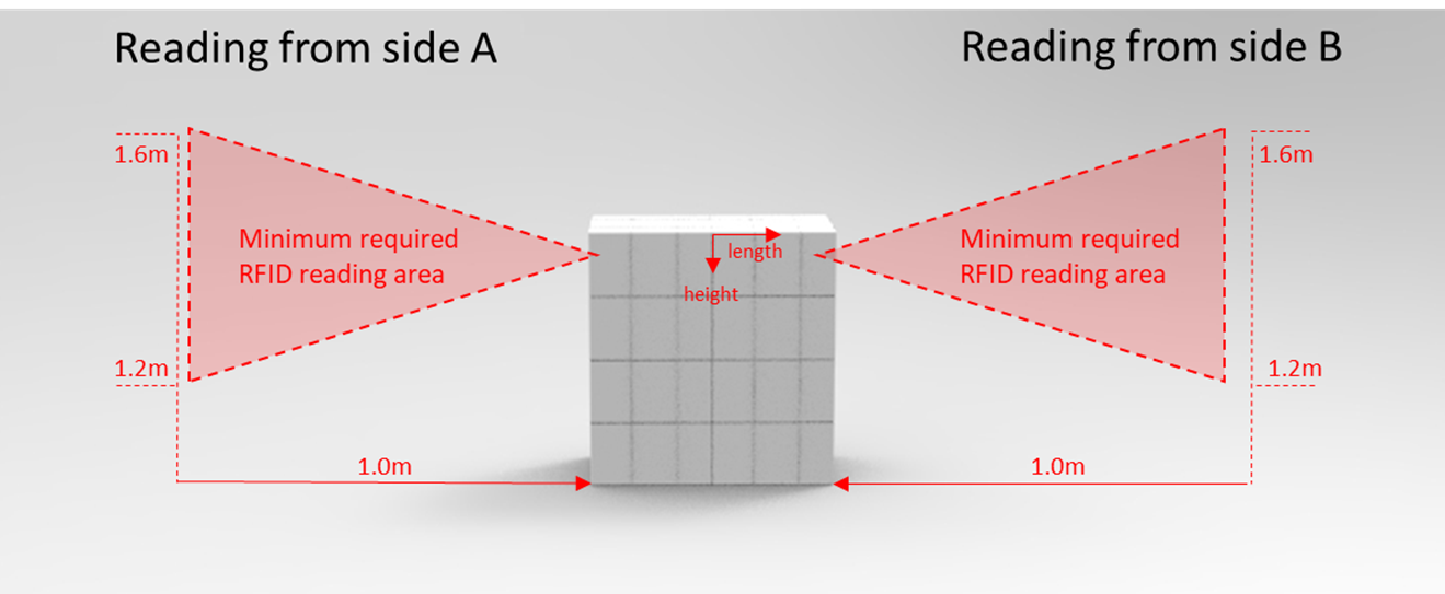
Reading of RFID tags must be possible at minimum, in the area between vertical position 1.2m and 1.6m from ground at 1.0m distance from the pulp unit surface
□ Antenna should be placed facing directly towards the bale surface at midpoint of the bale in performance testing scenario presented in Figure 4‑2 Reading areas of pulp unit from side view
□ Reading field may be narrower when reading from a closer range to the bale, due to field of view characteristic of the tag
■ Reading must be possible from 2 sides opposite to each other of the bundled pulp units (side A and side B, see below figures)
□ Reason for requirement is due to efficiency of forklift operations (pickup and loading must be possible from 2 sides)
■ Reading must be possible from a total width area of 1.0m measured at distance of 1.0m from the surface of a pulp unit, compared to the centreline of the bales. See the defined area (Figure 4‑1 Reading areas of pulp unit from top view)
□ Reader antenna should be placed at height of 1.2m in a performance testing scenario presented in Figure 4‑1 Reading areas of pulp unit from top view
■ Reading of tags may be possible also from other areas, angles/orientations and from longer distances, this document defines only minimum requirements.
Figure 4‑1 Reading areas of pulp unit from top view
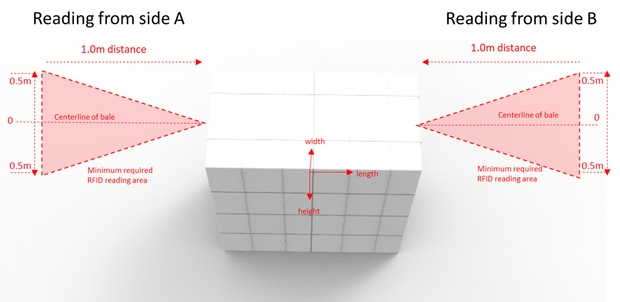
Figure 4‑2 Reading areas of pulp unit from side view
Reading of RFID tags must be possible at minimum, in the area between vertical position 0.2m and 0.6m from bale’s floor level at 1.0m distance from the bale surface
□ Antenna should be placed facing directly towards the bale surface at midpoint of the bale in performance testing scenario presented in Figure 4‑3 Reading from side (individual bale)
□ Reading field may be narrower when reading from a closer range to the bale, due to field of view characteristic of the tag
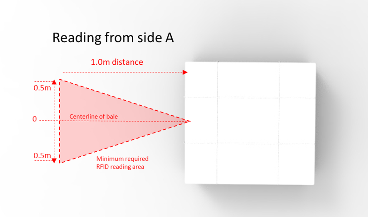
■ Reading must be possible from a total width of 1.0m compared to centreline of the bale. See the defined area in Figure 4‑4 Reading of bale from top view (individual bale)
□ Reader antenna should be placed at height of 0.4m in a performance testing scenario presented in Figure 4‑4 Reading of bale from top view (individual bale)
■ Reading of tags may be possible also from other areas, angles/orientations and from longer distances, this document defines only minimum requirements.
Figure 4‑3 Reading from side (individual bale)
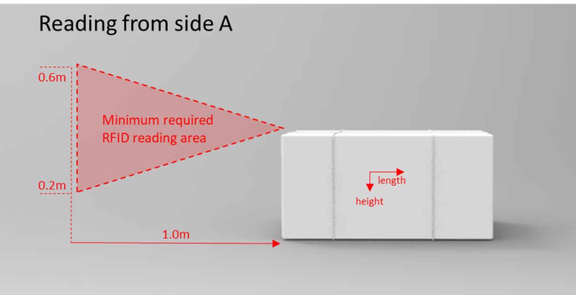
Figure 4‑4 Reading of bale from top view (individual bale)
5 Tag encoding, SGTIN-96 format
Tag encoding is recommended to be implemented using GS1 SGTIN-96 format. See latest version of Tag Data Standard [1] for details.
Permalocking of the EPC memory bank is recommended to secure the stored EPC code.
Table 5‑1 Structure of SGTIN-96
6 Example Tag Encoding
This section provides an example of tag encoding based on the following GS1 element string:
(01) 0 6400001 00123 7 (21) 10999991230
· An indicator of 0 (FOOTNOTE: this is not technically an indicator, but rather a leading 0)
· A GCP of 6400001
· An item reference of 00123
· A serial number of 10999991230
This GS1 element string is converted into an EPC Pure Identity URI (as used in EPCIS), as follows:
urn:epc:id:sgtin:6400001.000123.10999991230
While the EPC Pure Identity URI (as used in EPCIS events) is data-carrier-agnostic, the EPC Tag URI is a URI string that denotes a specific EPC together with specific settings for the control information found in the EPC memory bank. The EPC Tag URI is typically used at the data capture level when reading from an RFID tag in a situation where the control information is of interest to the capturing application. It is also used when writing the EPC memory bank of an RFID tag, in order to fully specify the contents to be written. By way of example, “Tag” URIs are leveraged by GS1's Application Level Events (ALE) interface standard, both as an input (when writing tags) and as an output (when reading tags).
The SGTIN in this example is encoded into an RFID tag as an SGTIN-96 EPC binary encoding. In this example, the item to be identified is a single bale. Therefore, the filter value is 0. The corresponding EPC Tag URI is as follows:
urn:epc:tag:sgtin-96:0.6400001.000123.10999991230
and the binary encoding in the EPC memory bank (MB 01) of the tag (starting at address 20hex) is:
301586A004001EC28FA68BBE (hexadecimal)
All the fields required to build the binary data to be encoded in the RFID tag are summarized in the Table below. The reader of this document can make use of the encoder/decoder tools available at https://www.gs1.org/services/epc-encoderdecoder in order to simplify the translation work.
Table 6‑1 Example of SGTIN-96
7 References and Glossary:
For the latest GS1 Glossary and terms please see www.gs1.org/glossary
1. EPC Tag Data Standard https://www.gs1.org/standards/epcrfid-epcis-id-keys/epc-rfid-tds/1-13
2. EPC UHF Gen2 Air Interface Protocol https://www.gs1.org/standards/epc-rfid/uhf-air-interface-protocol
3. EPC Compliant Class-1 Generation-2 UHF RFID Devices Conformance Requirements https://www.gs1.org/standards/epc-rfid/uhf-air-interface-protocol
4. ETSI EN 302 208-2 V2.1.1 https://www.etsi.org/deliver/etsi_en/302200_302299/30220802/02.01.01_60/en_30220802v020101p.pdf
5. FCC part 15.247 & 15.249 https://www.govinfo.gov/content/pkg/CFR-2013-title47-vol1/pdf/CFR-2013-title47-vol1-sec15-247.pdf , https://www.govinfo.gov/content/pkg/CFR-2009-title47-vol1/pdf/CFR-2009-title47-vol1-sec15-249.pdf
A Appendix
A.2 Bundled pulp unit, horizontal read range
Test results for Performance requirements for bundled pulp units (bundled bales) Figure 4‑1 Reading areas of pulp unit from top view
SIDE A)
Antenna orientation facing towards bale surface, vertical height 1.2m
SIDE B)
Antenna orientation facing towards bale surface, vertical height 1.2m
A.3 Bundled pulp unit, vertical read range
Test results for Performance requirements for bundled pulp units (bundled bales) Figure 4‑2 Reading areas of pulp unit from side view
SIDE A)
Antenna orientation facing towards bale surface, placed on centreline of the bale.
SIDE B)
Antenna orientation facing towards bale surface, placed on centreline of the bale.
A.4 Single pulp bale, horizontal read range
Test results for Performance requirements for individual pulp bales Figure 4‑4 Reading of bale from top view (individual bale)
Antenna orientation facing towards bale surface, vertical height 0.4m
A.5 Single pulp bale, vertical read range
Test results Performance requirements for individual pulp bales Figure 4‑3 Reading from side (individual bale)
Antenna orientation facing towards bale surface, placed on centreline of the bale.
Result of the compliance testing summarized:
Contributors & Change Log
Contributors
Log of Changes
Useful Links:
* PDF version of the GS1 RFID Identification of Pulp Products Guideline